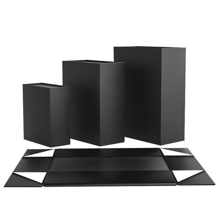




Exposed greyboard deserves a closer look than “normal production variation.” Here’s how to diagnose corner defects, build coverage into the dieline, and approve wrapping that holds up beyond the sample room.
Corners expose shortcuts.
When a rigid box carries a premium price but its wrapping paper stops short of the board at the corner, I would examine the dieline, material specification, and production settings before accepting an explanation about unavoidable handwork.
What, exactly, is premium about visible greyboard?
To avoid exposed edges in rigid box wrapping, provide sufficient corner coverage for the actual board and wrap thickness, control cutting and positioning variation, and secure the folds within the adhesive’s working window. Verify the result after setting, including the inner turn-ins and lid-contact areas.
My position is straightforward: “make the corners cleaner” is a complaint. A controlled corner drawing, an approved material combination, and measurable acceptance criteria give the factory something it can reproduce.
A white line on a black box does not automatically mean the greyboard is exposed. Start by identifying which layer is visible.
| Visible symptom | Likely explanation | First check | Correction to investigate |
|---|---|---|---|
| Grey triangle between corner flaps | Insufficient overlap or misplaced wrap | Open a rejected sample and inspect the cuts | Revise tab geometry, cut position, or registration |
| White strip on otherwise intact paper | Printed color stops before the required coverage area | Compare artwork with the assembled wrap | Extend artwork coverage and confirm print registration |
| Jagged white line along a bend | Paper, coating, or surface finish has fractured | Inspect the fold under magnification | Trial paper direction, finish, and folding conditions |
| Corner looks covered initially, then lifts | Inadequate bond or fold springback | Check adhesive transfer and setting conditions | Adjust adhesive compatibility, timing, or holding pressure |
| Bare board along the inside rim | Insufficient or displaced turn-in coverage | Inspect the rim and liner junction | Revise turn-in depth, placement, or liner coverage |
These are diagnostic starting points, not automatic verdicts. Several defects can occur together.
And there is a practical reason to sacrifice a rejected box: unfolding the corner reveals whether the material was missing, misplaced, fractured, or simply unbonded. A photograph rarely settles all four questions.

The wrap has to fit the physical shell, including its board thickness, corner joints, and assembly variation.
A specification reading “2.0 mm greyboard” describes one component. It does not establish the finished distance the covering paper must travel around a corner.
Before approving the wrap dieline, I would require confirmation of:
This belongs in the rigid box structural design and engineering review, while the geometry can still be changed economically.
Il Paperboard Packaging Council’s rigid-box manufacturing explanation identifies trimming, or mitering, the wrap corners as part of converting a flat covering into a finished box.
But “miter the corner” is an incomplete production instruction.
For a construction using an angled cut, the cut must leave enough material to cover the board corner after folding. Other constructions rely on shaped tabs or overlapping flaps. Copying a familiar 45° cut without checking the assembled result can remove the material needed to conceal the core.
My recommendation: make a dry assembly to inspect coverage and bulk, then repeat with the intended adhesive and production sequence. The bonded sample is the approval reference.
Consider this illustrative worst-case calculation, not a set of recommended factory tolerances:
Remaining coverage: 1.2 − 0.5 − 0.4 − 0.4 = −0.1 mm
The nominal drawing shows an overlap. The combined variation produces a gap.
Actual tolerances must come from process measurements. Still, the lesson is useful: corner coverage needs enough margin to survive the agreed variation, without creating a bulky seam that affects appearance or lid fit.
Printed bleed extends color beyond a trim boundary. Physical wrap allowance supplies paper for folds, overlaps, and turn-ins.
They solve different problems.
If intact white paper appears at the edge, review print coverage. If a gap exposes greyboard, extending the ink will leave that gap intact.
Coordinate both through the packaging artwork and dieline review, using an assembled sample to confirm where the printed surface actually lands.
Grammage measures mass per area. It does not fully describe thickness, flexibility, coating behavior, or resistance to folding damage.
Per coated paper rigid box packaging, I would approve the finished material combination: paper, printing, coating or lamination, adhesive, and folding sequence.
A successful trial on unfinished stock leaves an unanswered question about the final surface.

Historical data in the USDA Forest Products Laboratory’s paper on dimensional stability illustrate why paper direction matters: for bond paper exposed to a change from 25% to 65% relative humidity, the reported expansion was 0.11% in the machine direction e 0.48% across it.
Across a 100 mm span, those percentages correspond to 0.11 mm and 0.48 mm respectively. These historical figures are not tolerances for your wrap stock; they show why moisture and orientation deserve investigation when a previously acceptable corner starts drifting.
Record material-conditioning and production conditions. Compare samples after the agreed adhesive-setting period, rather than judging every box immediately after pressing.
In a study published on 18 March 2026, LUT University researchers tested MetsäBoard Prime FBB EB, un 226 g/m², 346 μm dispersion-coated paperboard, using steel, polytetrafluoroethylene (PTFE), and polyoxymethylene (POM) creasing rules; microscopy showed less surface damage with the plastic rules than with steel. The published experiment demonstrates that tool–material interaction can change the damage produced during conversion.
An industrial study published on 18 September 2026 then tested three dispersion-coated paperboards on a Ruiyang ML1200 die cutter. The research published by BioResources at North Carolina State University found the highest oil and grease resistance with PTFE rules for two boards, while POM’s average performance was comparable to steel; the third board’s damage prevented a meaningful comparison across rules.
Both studies concern barrier-coated folding boxboard. Their findings do not establish settings or defect-reduction rates for decorative rigid-box wraps.
My inference for rigid box wrapping is narrower: investigate the material, direction, and contact conditions before assuming that greater pressure will improve a damaged fold.
For a wrapping trial, I would record the adhesive grade, application amount, application temperature where relevant, open time, holding pressure, and setting conditions against the supplier’s recommendations.
If the dry assembly provides coverage but the bonded corner lifts, investigate adhesive transfer, wetting, timing, and fold springback.
Adding glue without identifying the cause introduces another variable. It may also leave the appearance problem unresolved.
A beautiful sample proves that the construction can be made. Production approval also needs evidence that the agreed process can repeat it.
Utilizzo production-material samples and packaging prototypes to inspect the actual paper, finish, adhesive, and assembly method wherever practical. Document substitutions before treating a sample as the production benchmark.
For rigid box edge finishing, I would put these requirements into the approval brief:
Keep the appearance requirement separate from lot acceptance. “No visible exposed board” describes an individual box; the sampling plan determines how the shipment is assessed.
I would also retain labeled acceptable and unacceptable corner samples. “Premium finish” leaves too much room for argument.

Rigid box corner wrapping is the process of folding and bonding a decorative covering around the junction of rigid board panels, with coordinated corner tabs, overlaps, and turn-ins that conceal the core while keeping the finished corner flat, secure, and visually consistent.
Preventing exposed edges on rigid boxes means specifying enough physical wrap coverage for the actual board thickness, preserving the corner overlap after cutting and positioning variation, and bonding the folded paper securely, with the finished result checked after the adhesive has set under agreed conditions.
A rigid box corner miter allowance is the clearance between the board corner and the angled cut in the covering paper, selected for the board thickness, wrap thickness, corner construction, and folding sequence so that trimming removes excess bulk without opening a gap.
Approve the allowance on the actual construction and finished materials rather than applying one number to every box.
White corners on dark rigid boxes are visible pale areas caused by incomplete printed coverage, fractured paper or coating, or exposed board or liner, and each condition requires a different correction because extra ink, more adhesive, and larger corner tabs address different underlying failures.
Send XD Packaging your rigid box design brief with the box style, dimensions, board thickness, wrap material, finish, order quantity, and close-up photographs of any existing defects.
Request a dieline review and a production-material sample showing both exterior corners and inner turn-ins. Agree on the coverage, bonding, and fit requirements before authorizing the production run.